CURABITUR ALIQUET QUAM POSUERE
Welcome Aboard Us!
Subscribe to our emails for the latest industry updates and special offers.
Will be used in accordance with our Privay Policy

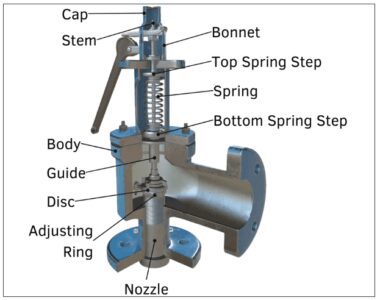
The design details of a relief valve body are critical to the safety of a pressure vessel. This article will look at three critical holes in the valve body: drain holes, drain holes, and adjustment screws, which are essential to ensure the proper operation and maintenance of the safety valve.
The discharge holes are designed to reduce the impact of medium deposits and fouling on the safety valve performance. For safety valves used with steam and liquid media, the drain hole shall be located at the lowest liquid collection point below the sealing surface of the valve seat.
According to the provisions of Article 4.4.5 of GB/T 122432021 “Spring direct Load type safety valve”, the diameter of the discharge hole shall meet the following standards:
The nominal diameter of the safety valve is greater than 65mm, and the diameter of the discharge hole shall not be less than 9.5mm.
The nominal diameter of the safety valve is less than or equal to 65mm, and the diameter of the discharge hole shall not be less than 6.5mm.
If the safety valve is not equipped with a discharge hole or is not used in practical applications, tear holes should be set in the pipeline near the outlet of the safety valve to prevent fluid accumulation affecting the performance of the safety valve.


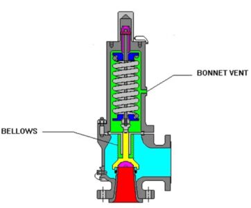
The cover of the bellows safety valve must be provided with an outlet hole to keep the bellows cavity connected to the atmosphere. For flammable or corrosive media, the discharge hole should be connected to the safe site through the pipe to prevent the media from leaking after the bellows are damaged.
The discharge hole comes with a temporary dust-proof plastic plug, which must be removed during operation to prevent pressure buildup in the valve cover from causing the bellows to fail. To prevent impurities from entering the valve cavity, it is recommended to install a vent elbow with a dust cover. In order to ensure the versatility of the valve cover, some manufacturers will plug the discharge hole on the cover of other types of safety valve with a wire plug to form a closed valve cover.


Safety valve adjustment screws are usually located on the upper or side of the valve body, depending on the model. The arrow marked with the adjustment direction on the adjustment screw increases the opening pressure when tightened. Otherwise, it decreases.
In order to prevent the adjustment mechanism from loosening and arbitrarily changing the adjusted state, the safety valve must be equipped with an anti-loosening device. The external adjusting mechanism should be provided with a seal part, which should be sealed after debugging to ensure that the adjustment state is not changed at will. After disassembly, reassembly and debugging, the seal should be re-sealed, and the seal design should be adjusted after damage.
Critical holes in the valve body of a relief valve are essential to ensure the safety and reliability of the relief valve. Correct design, installation and maintenance of these holes can effectively prevent the occurrence of safety accidents and ensure the safe operation of industrial production.
Through careful management and maintenance, we can ensure that these critical components play their proper role, thereby maintaining the safety and stability of the entire system.